
Thermal Behaviour
The thermal behavior of electronic components refers to how these components generate, transfer, and respond to heat during operation. It involves the study of temperature rise due to power dissipation, and the impact of temperature on the component’s performance, reliability, and longevity.
Heatsink
General Purpose Heatsink
A heatsink is a device used in electronics to absorb and dissipate heat from electronic components, preventing them from overheating and ensuring reliable operation. It is typically made of metals with high thermal conductivity, such as aluminum or copper, and increases the surface area available for heat dissipation to the surrounding air.
PCB Heatsink
In PCB design, a heatsink can be a physical component or a specially designed area on the circuit board, such as large copper pads, thermal vias, or copper pours. These features help absorb and dissipate heat, prevent overheating, and ensure reliable operation.
Heatsinks Used
We compared two different types of heatsinks on the LM317 IC. First, we used a PCB-type heatsink on the LM317 IC as shown in Fig. 2.3(a). Second, we used a metallic heatsink as shown in Fig. 2.3(b). We also compared performance without any heatsink as shown in Fig. 2.3(c).
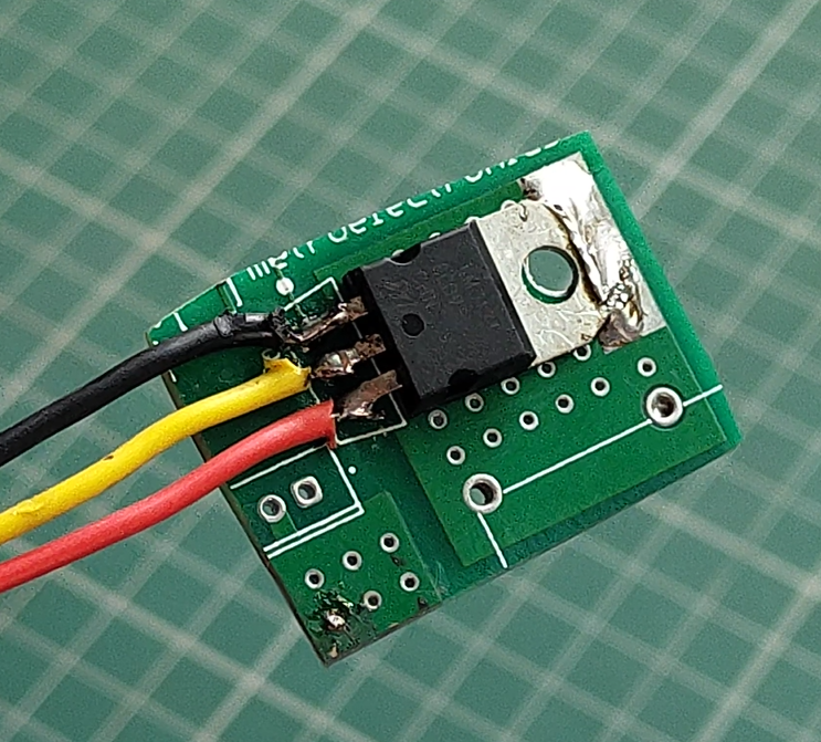
Fig 2.3(a)
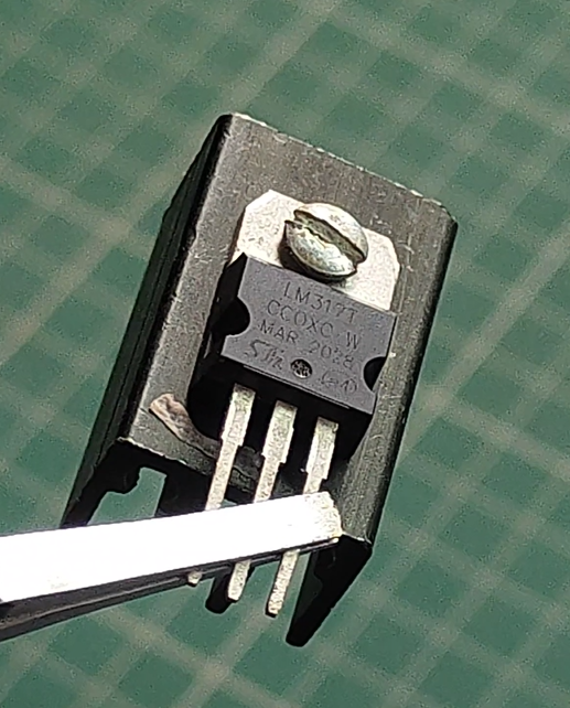
Fig 2.3(b)
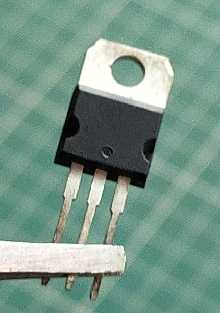
Fig 2.3(c)
Connection
The circuit is connected based on Fig. 3.0(a). In this circuit diagram, R1 and R2 are adjustable resistors used to set the output voltage. The LM317 pin configuration is as follows: the first pin is Adjust, the second is Output, and the last is Input. A load resistor is connected across the output terminal and ground. Fig. 3.0(b) shows the connection.
For this experiment, the input voltage is 24 V, the output voltage is 5 V, and the load current is 60 mA across a 220 Ω load resistor.
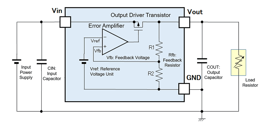
Fig 3.0(a)
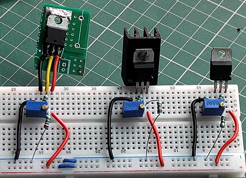
Fig 3.0(b)
Thermal Activity
The thermal behavior of the IC was recorded using a thermal camera with heatsinks and without heatsinks. The ambient temperature was 37 °C. Thermal images of all three configurations at saturated temperatures are shown in Fig. 4.0(a), Fig. 4.0(b), and Fig. 4.0(c).
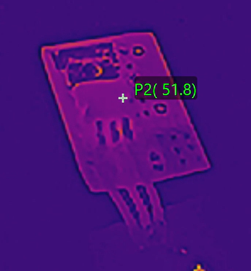
Fig 4.0(a)
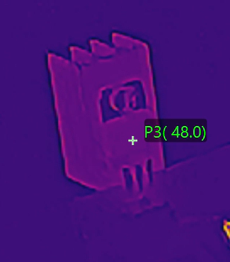
Fig 4.0(b)
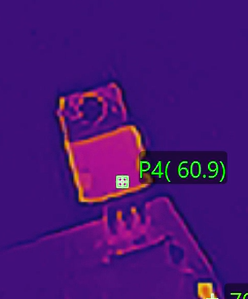
Fig 4.0(c)
Temperature rise is the difference between ambient temperature and the component temperature. It indicates how much the component’s temperature increases due to heat dissipation.
A graph of Temperature vs. Time was also plotted in Fig. 4.0(d) to better understand the thermal behavior.
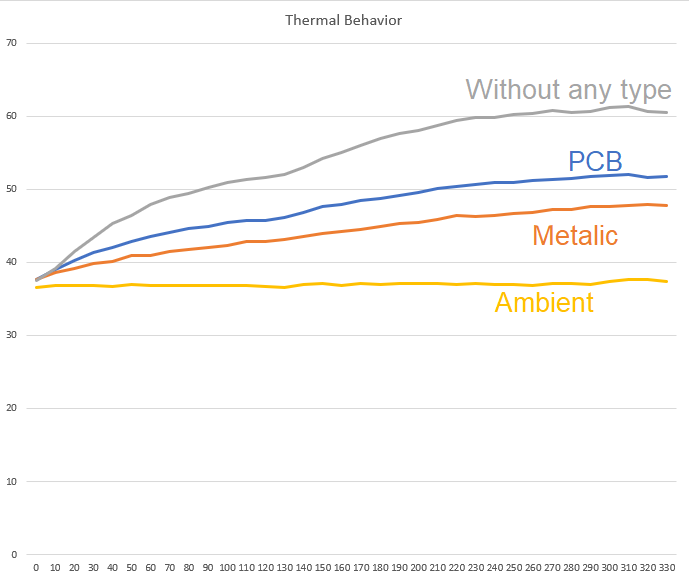
Fig 4.0(d)
Source of Heat Generation and Voltage Drop
The internal circuit diagram of a linear voltage regulator shows what appears to be a variable resistor, but it is actually a transistor. This transistor acts as a variable resistor and is responsible for both voltage drop and heat generation. It functions like a water tap, dropping voltage by dissipating excess energy as heat.
If load current increases, or if the difference between input and output voltage is large, the regulator’s temperature rises significantly.
Precautions and Methods for Heat Control
- Increase the surface area of the metallic heatsink.
- Increase the copper area of the PCB.
- Add thermal vias on the PCB.
- Expose PCB copper layers to the environment for better heat transfer.
- If possible, connect the linear voltage regulator to a nearby metal chassis, ensuring proper electrical isolation.
- Reduce the voltage difference between input and output whenever possible.
- Use a switching regulator before the linear regulator to reduce dissipated power.
- Place the regulator near the PCB edge for better airflow.
- Use active cooling methods such as a fan.
Conclusion
This experiment shows that the type of heatsink used with a linear voltage regulator like the LM317 significantly affects its thermal performance. A metallic heatsink keeps the IC coolest, a PCB heatsink offers intermediate effectiveness, and using no heatsink results in maximum heat buildup. Excessive heat can damage the regulator and impair its performance.
To maintain safe and efficient regulator operation, it is important to use a suitable heatsink, ensure adequate airflow, and reduce the difference between input and output voltages. Simple design improvements, such as increasing PCB copper area or using a cooling fan, can further enhance thermal management.
In summary, effective heat management is essential for the safe and reliable operation of linear voltage regulators.
Written by: Dhruv V. @ Ardra Lab